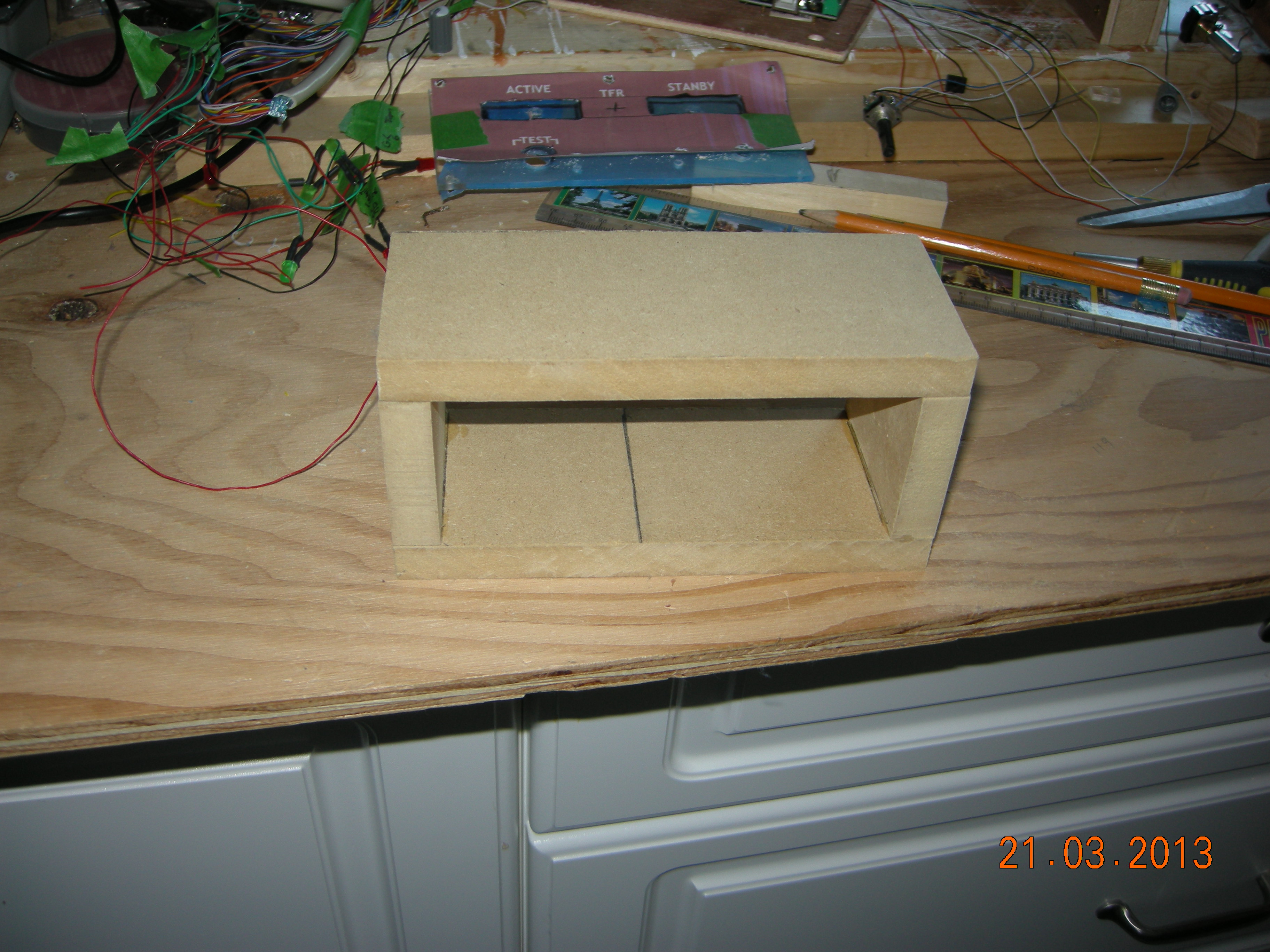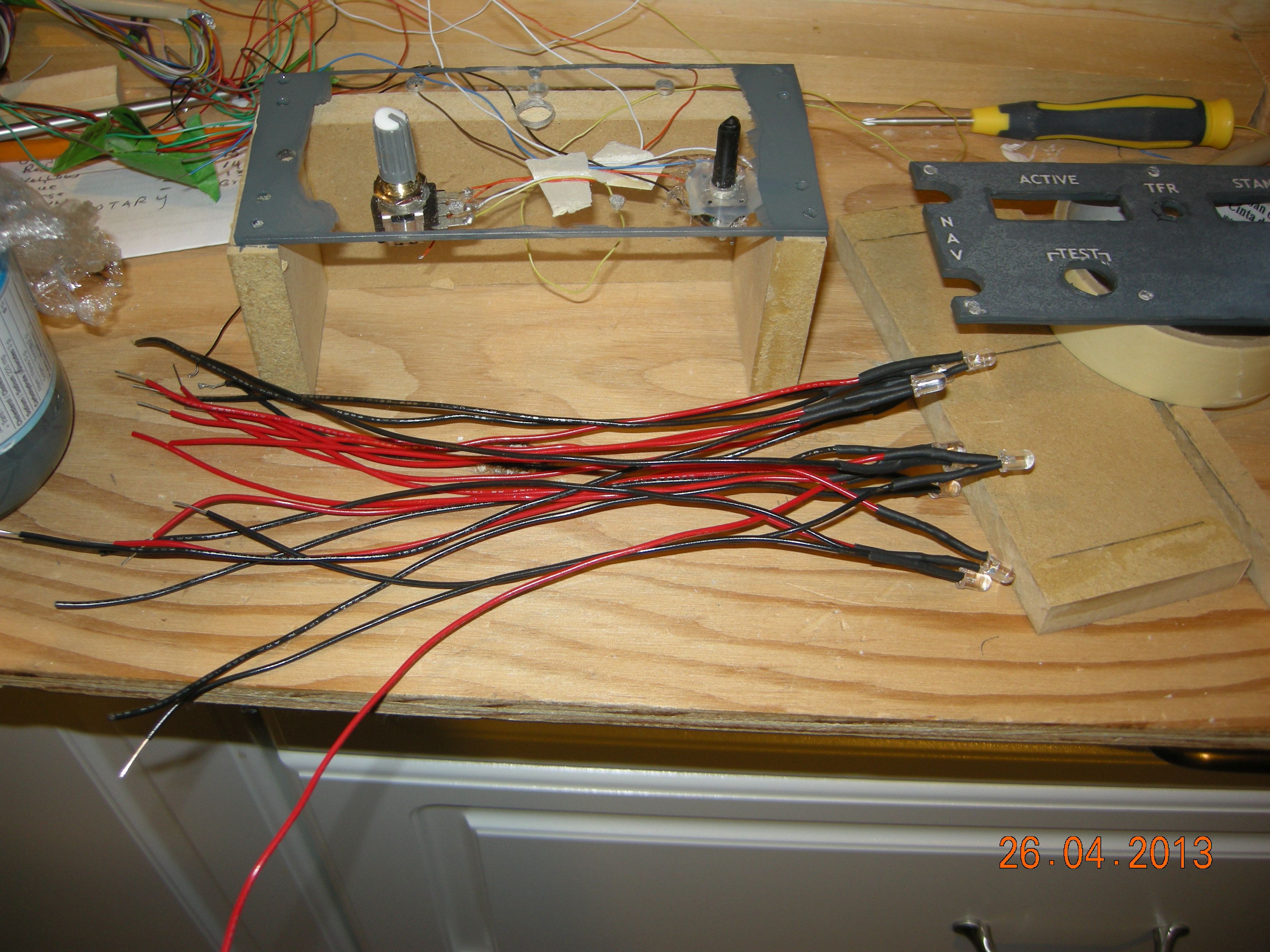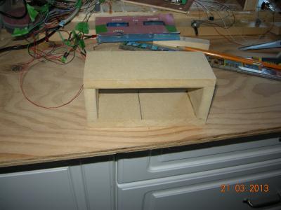
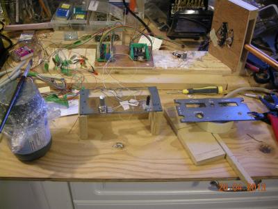
Built a rough box to house the prototype until I build a pedestal.
| 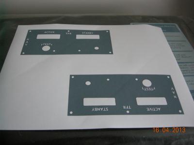
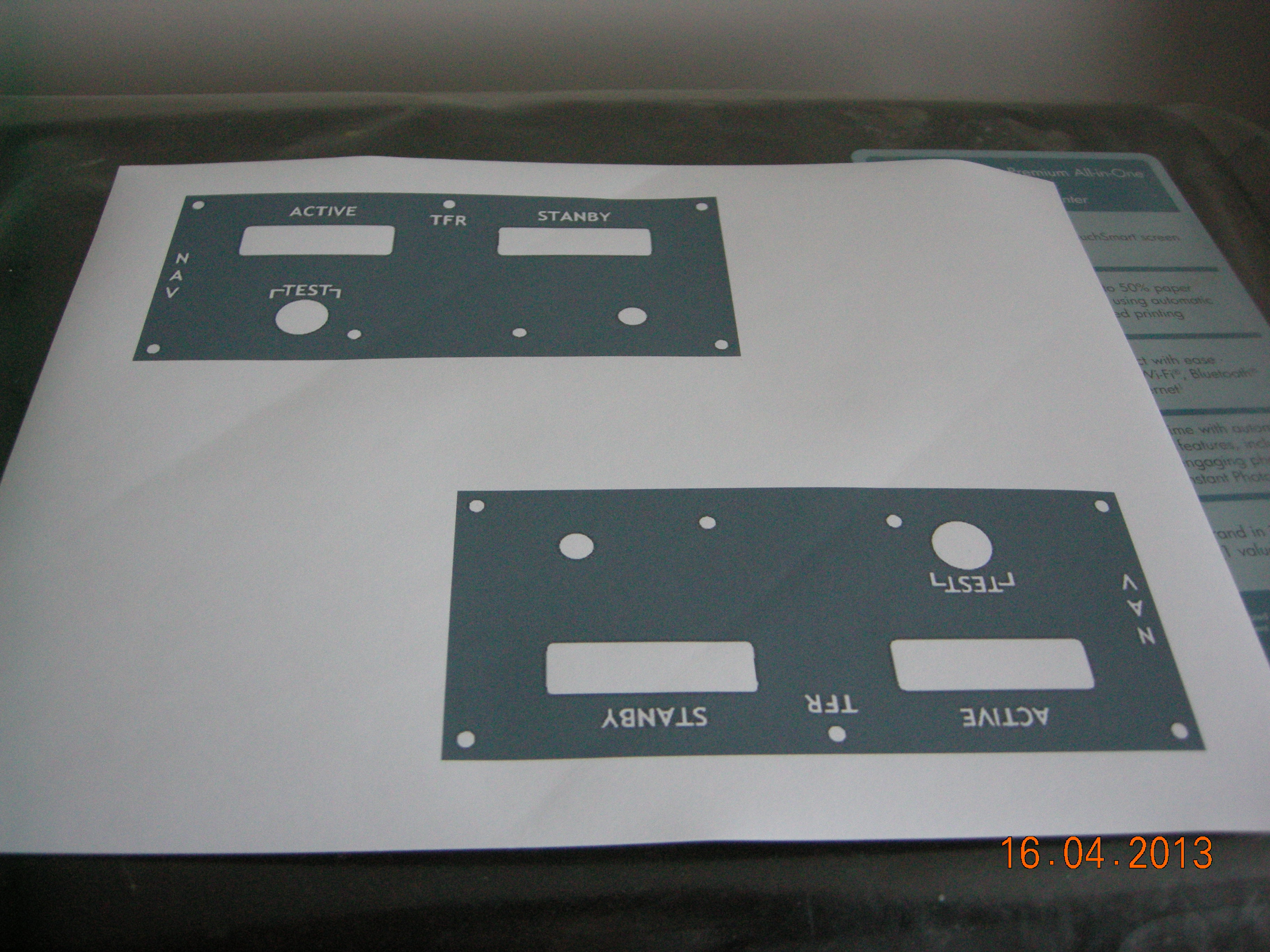
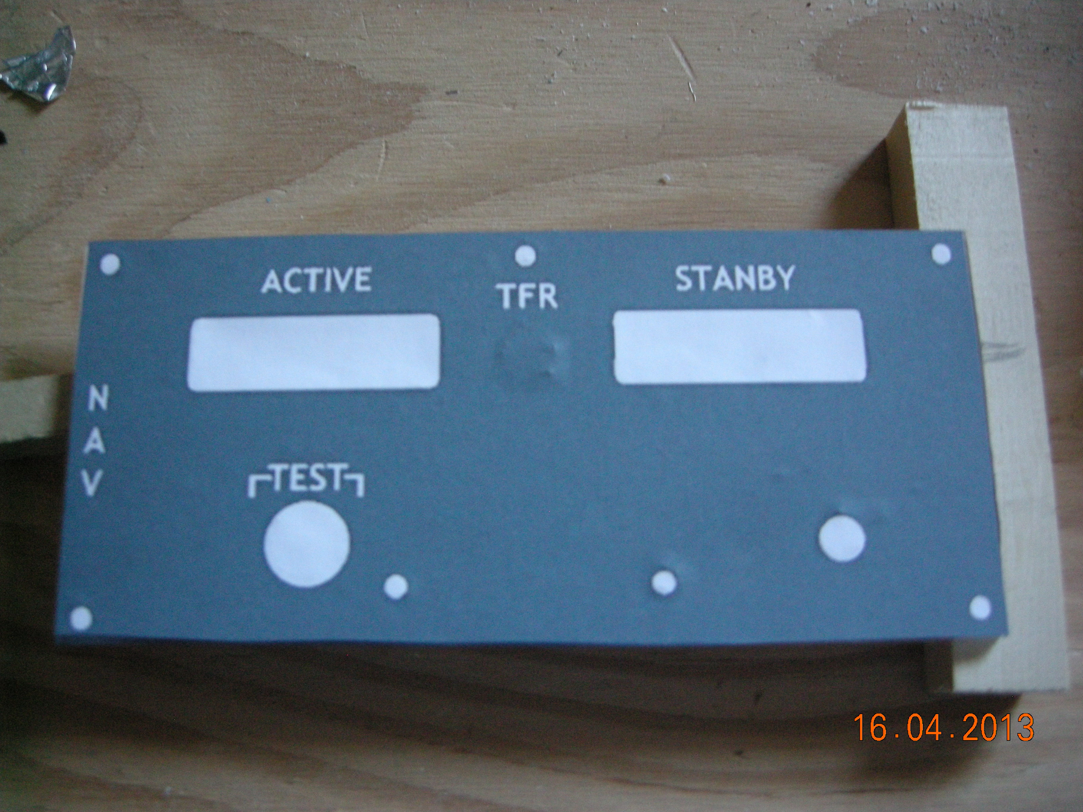
Print out the face plate images on sticky paper. Two images and
two plexi plates per radio. .
|

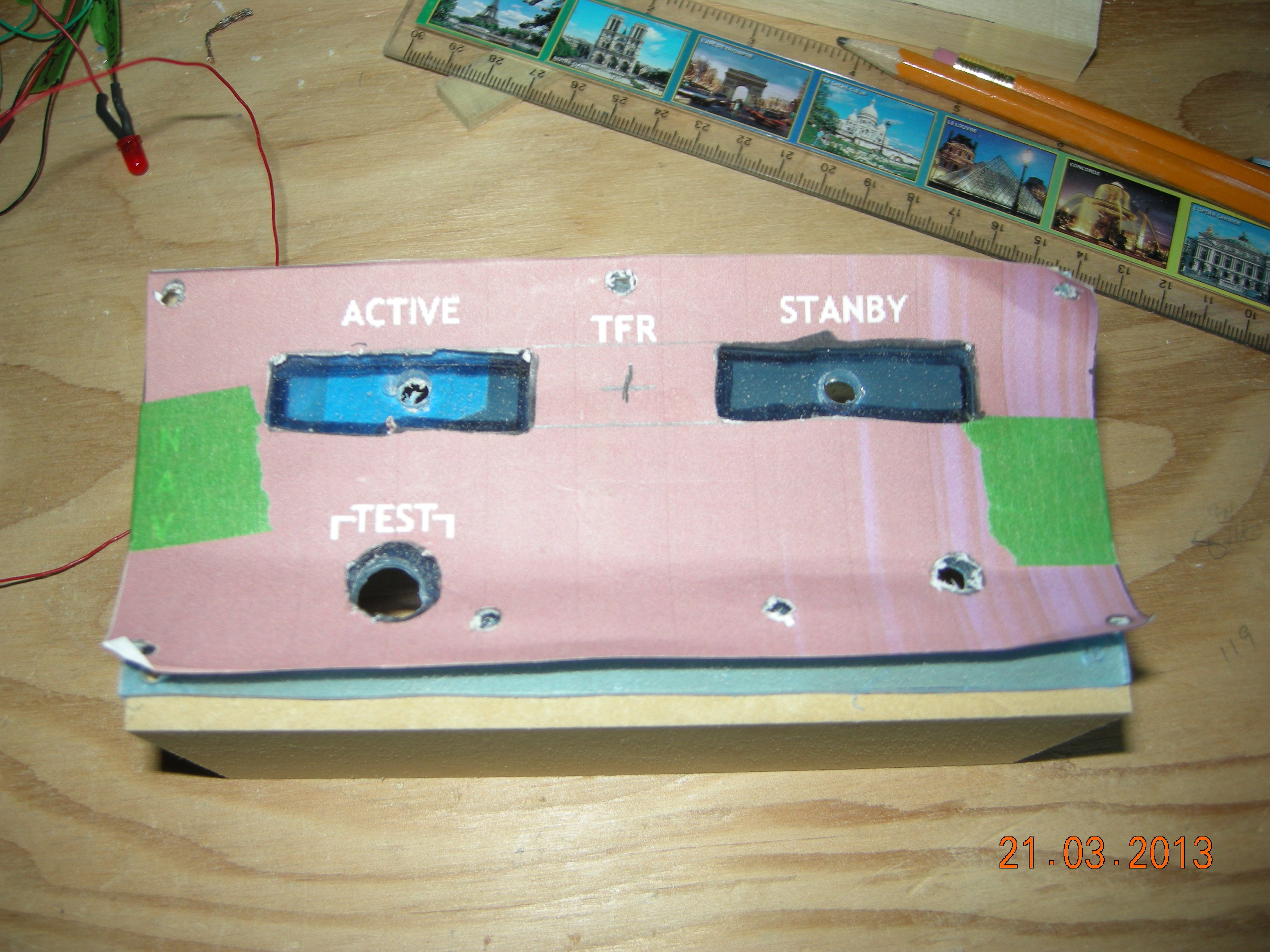
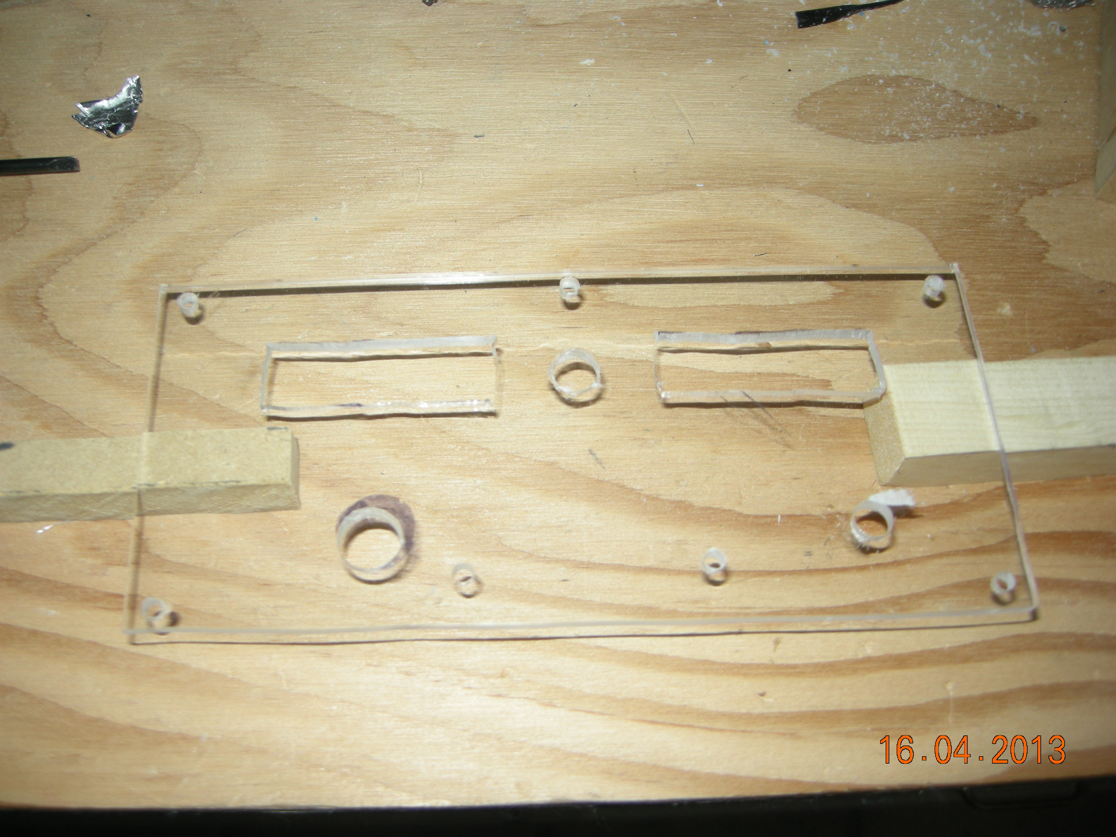
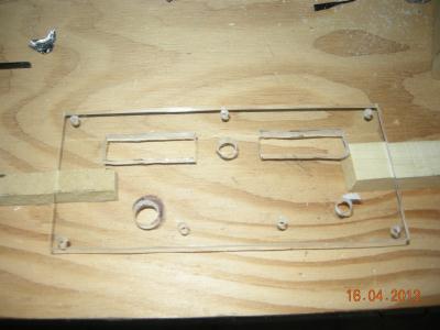
Tape on a template and drill out holes
to match template. I used a scroll saw to cut the square areas.
| 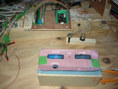
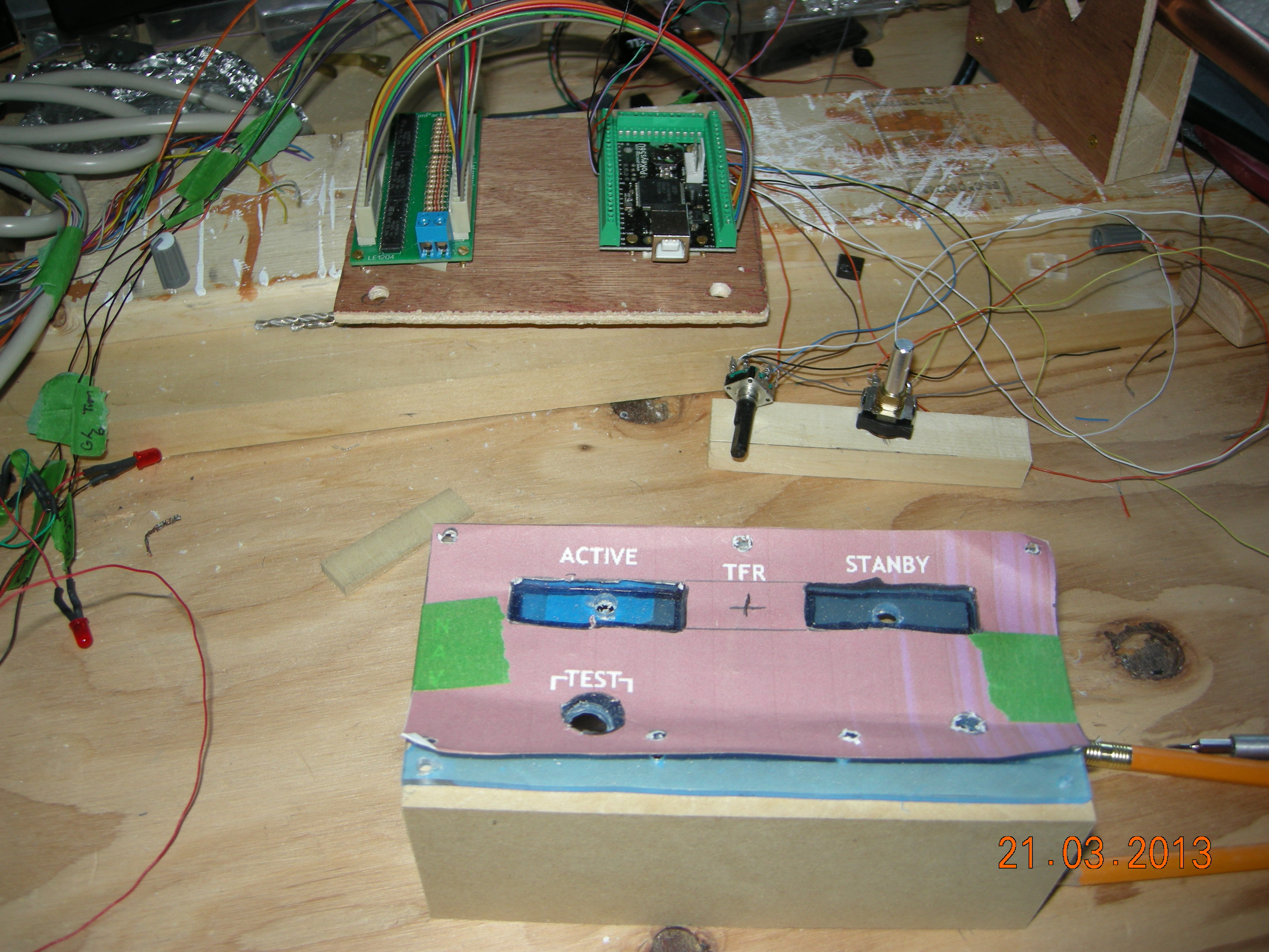
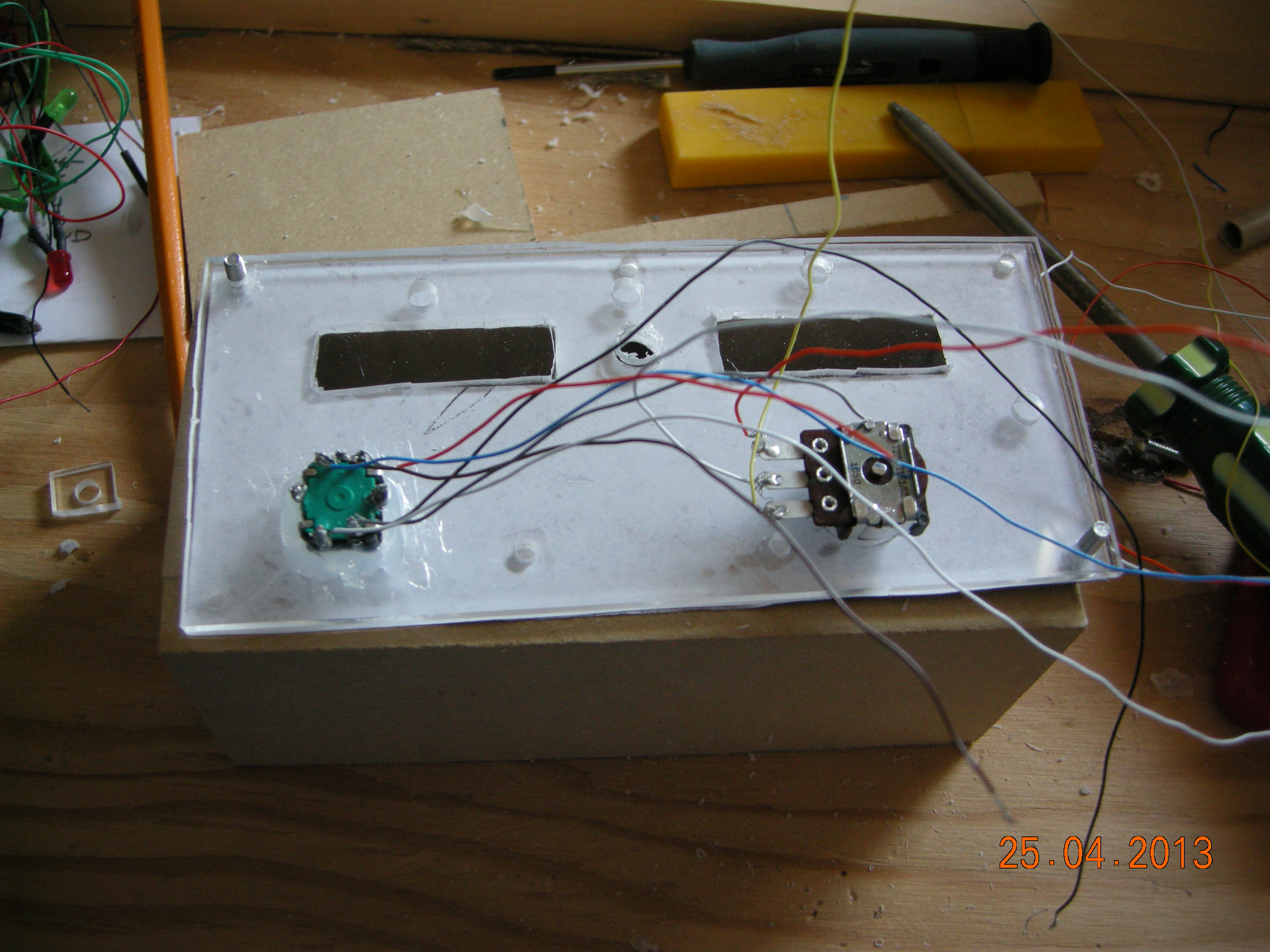
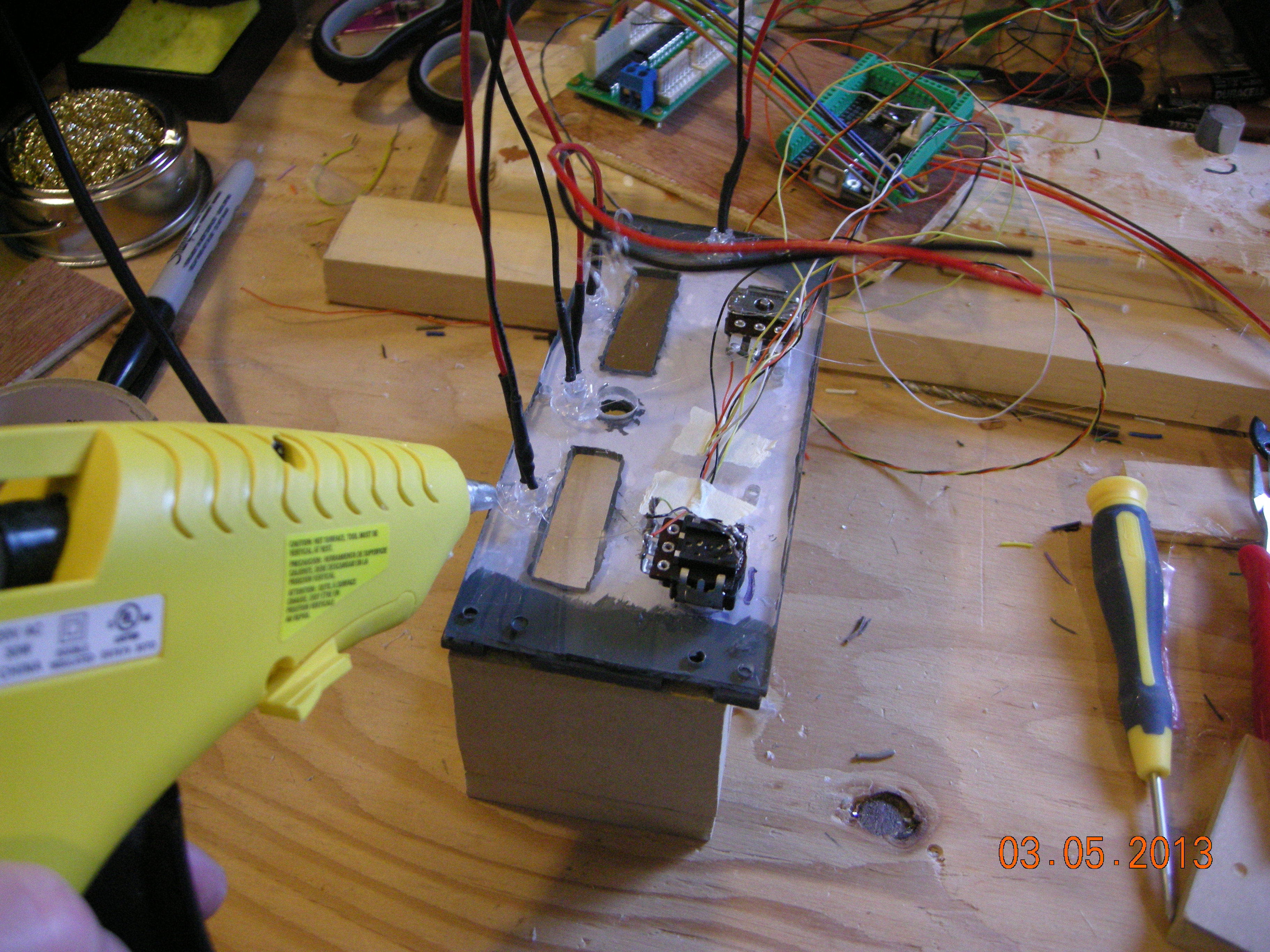
lining up a couple of rotary encoders for adjusting the radio digits.
Remember this is a prototype.
|
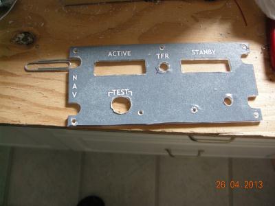
plexi plate drilled out.
| 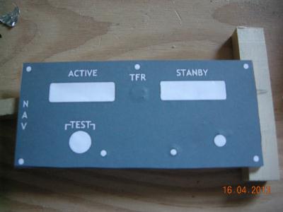
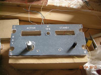
Remove the backing from the printout and align to the plate.
|

Installing rotary switches.
| 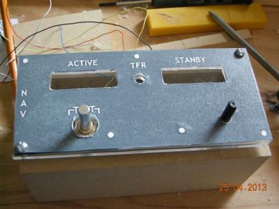
Please note, this is a prototype and the finished radio will have a
dual concentric encoder, and a test button will replace
the left side rotary switch..
|
A paper clip makes a good guide.
| 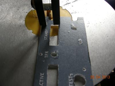
Cut out with scroll saw.
|
Checking the top and bottom plates for fit.
| 
Painting the plates.
|

Making up leds for backlighting
| 
Drilled small hole for each led and glued in place. This may be
overkill but will see later.
|